
Introduction
The purpose of this project was to work together as a team to analyse and design an app for one of two given scenarios. we choose to work on scenario A, which was for a batch chemical reactor system. The tank has two valves entering the system and then one delivery valve along with a heater a mixer and then beside them a temperature gauge and a vessel level gauge. The process starts when the on/ off switch is turned on. The emergency button is used to stop the program, in case of an emergency. The temperature gauge represents the number of contents in the tank.
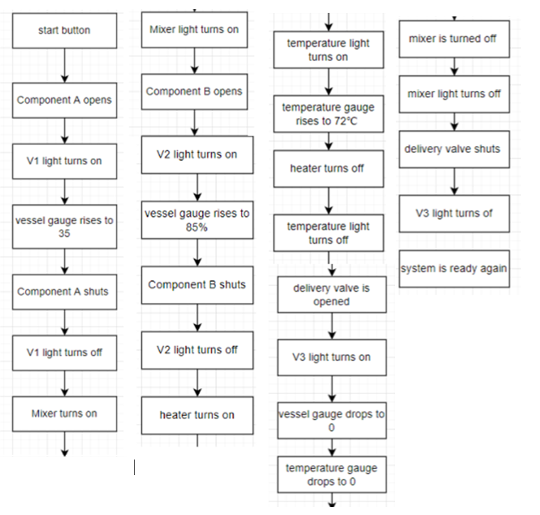
When the on/off switch has been flicked then valve 1 opens and the vessel is filled to 35%, once it reaches 35% motor 1 turns on and valve 2 opens and component be is added at the same time as the motor is on, the vessel gauge then rises to 85% and once 85% is reached then the temperature knob is now able to be adjusted previous it was disabled and now it is enabled and able to adjust so you can set the temperature to 72 degrees and once 72 degrees is hit the temperature then begins to drop to zero once reached valve 3 or delivery valve opens and the tank level gauge drops to zero as all the contents are being emptied, once emptied you are now able to flick the on/off switch and the process will start again.
Inputs And Outputs Components
Inputs
- On/off switch – This switch is used to start the process.
- Emergency stop button – This button is used in the event of an emergency, to stop the process.
- Temperature knob – This knob is used to control the temperature in the tank.
Outputs
- Start Button Lamp – This lamp turns on when the start button is on.
- Valve 1 Lamp – This lamp turns on when valve1 is open.
- Valve 2 Lamp – This lamp turns on when valve2 is open.
- Delivery Valve/ Valve 3 Lamp – This lamp turns on when valve3 is open.
- Heater Lamp – This lamp turns on when the heater is turned on.
- Mixer Lamp – This lamp turns on when the mixer is turned on.
- Temperature gauge – This gauge shows the temperature of the tank and is controlled by the temperature knob.
- Vessel level graph – This graph shows the contents of the tank and shows the tank increasing and decreasing.
Flowchart
Normal process cycle
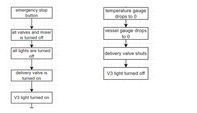
Emergency Stop Button
Process Description
To achieve the full functionality of our app, we used callback functions. These functions are triggered by events, and we were able to use these events to design the functions. We would describe the function and trigger of each of these functions.
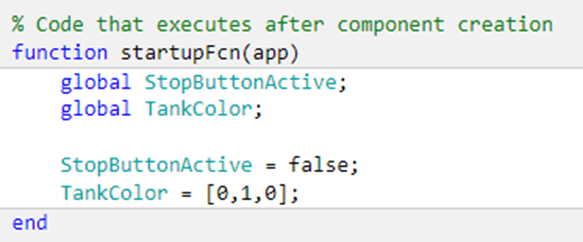
Function StartupFcn
This function runs at the start of the app. We created two variables global, stopButtonActive and Tankcolor. The stopButtonActive would be used to check if the stop button is on and it is false as default. The Tankcolor determines the colour of the content in the tank, and we set it to green.
Function Tempknobvaluechanging
This function allows the temperature knob to control the temperature gauge. It sets the value of the knob to be the same value shown on the temperature gauge. The heater Lamp shows the state of the heater. When the Changing value of the knob is greater than zero the colour of the heater lamp is green showing that the heater is on and when the Changing value of the knob is equal to 0 the colour of the heater lamp is red showing that the heater is off.

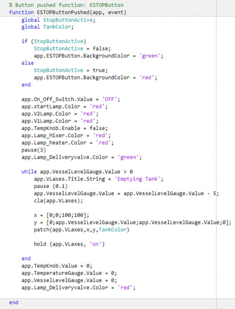
Function ESTOPButtonPushed
This function is triggered when the emergency stop button is pressed. When the emergency button is pressed, the function is supposed to shut down all the system components and remove the contents in the tank. To start the function, we declared the two global variables because they would play a part in the function. Then we put an if statement to set the background colour to reflect the state it is in. when the stop button is not active the colour would be green and when it is active the colour would be red.
Next, the On/Off button is set to off and the start lamp turns red. Then Valve 1, Valve 2, mixer, and heater are turned off. This is represented by their respective lamps turning red. Then Valve 3 is opened to allow the contents in the tank to exit the tank, this is represented by the delivery valve lamp turning green. We added a while loop to remove the contents in the tank and show it on the Vessel level graph. As the loop is repeated the content in the tank reduces and this is reflected on the Vessel level graph. When the tank is empty, Valve 3 is closed and the lamp turns red and the temperature is set to 0.
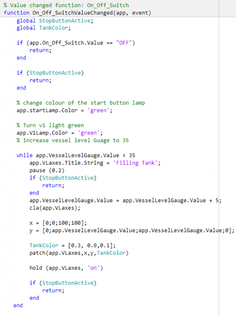
Function On_off_SwitchValuechanged
This function is triggered when the On/off switch is turned on. It describes the normal process cycle the mixing tank goes through. The if statements ensure that the process does not start when the switch is off or when the stop button is active.
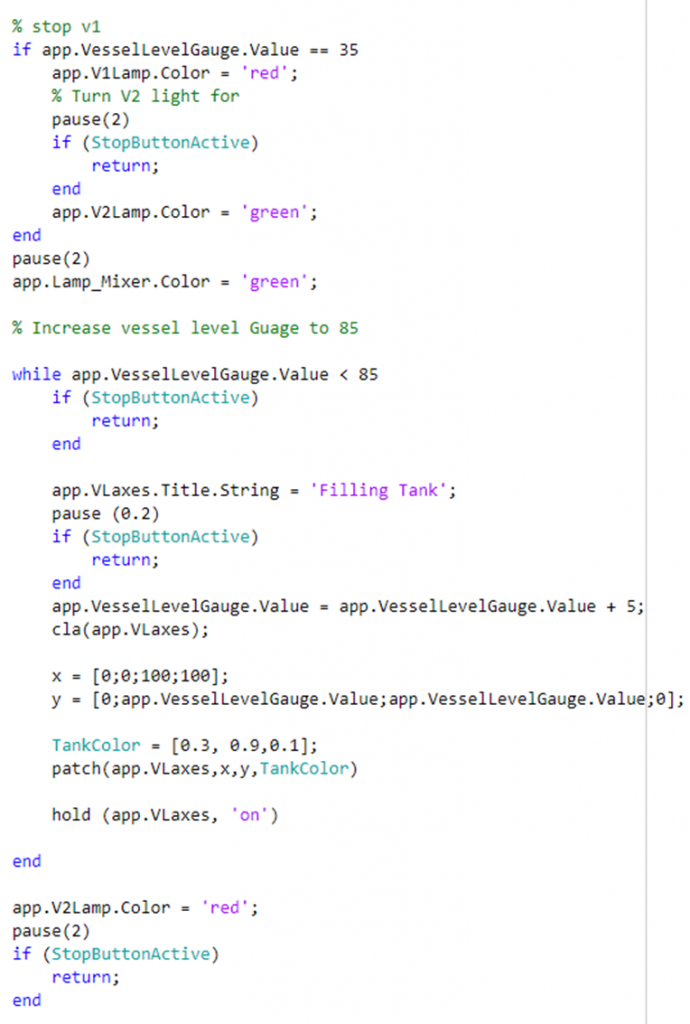
The process begins when the On/off switch is turned on, the start lamp turns green. Then, Valve1 is opened which is indicated with the Valve1 lamp turning green. The contents in the vessel begin to increase and this is shown on the Vessel level graph. This increase is done using a loop with the while statement, when the contents in the tank are less than 35%, it continues adding five till the tank reaches 35%. When the contents in the tank are equal to 35%, Valve 1 is closed this is indicated with the valve1 lamp turning red. Then Valve 2 is opened, which is represented by the Valve2 lamp turning green. At this stage, the content in the tank is filled to 85% using the second loop with a while statement, this allows the content in the tank to continue to increase by 5 till it reaches 85%. Once the content in the tank is at 85%, Valve2 is closed, and this is indicated by the Valve2 lamp turning red.
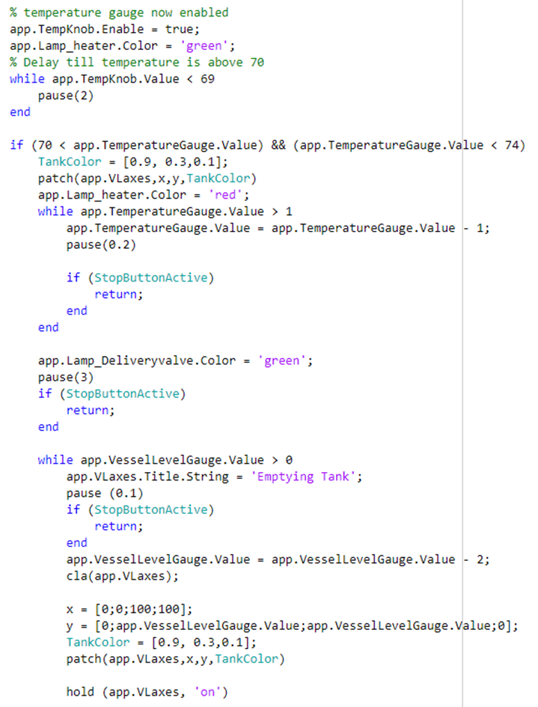
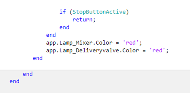
We were required to use an analogue input for the temperature, so at this stage, the temperature knob is active and would be used by the operator to control the increase in temperature. To account for any delays or time lost in turning the temperature knob, a pause loop was added using a while statement. The process would remain paused till the temperature is above 69. these would account for any time last in turning the knob. When the temperature is at 72 degrees the heater is turned off and the temperature begins to reduce. Delays or lost time when turning the knob could cause Matlab to skip this section of the code since the temperature is not yet up to 72. At this point the contents in the tank are hot, to indicate this change we included a change of colour, the tank colour is set to orange. Valve 3 is opened to remove the contents in the tank, this is indicated by the Valve3 lamp turning green. When the tank is empty Valve 3 lamp turns red and the On/off switch turns off, ready for the process to begin again.
Conclusion
During this process, we encountered a couple of problems but there were two major ones. The first was the emergency stop button, when the stop button completes its process, the program would return to where it was previously on the start button process sequence e.g would begin opening valve 1 or opening V2 or starting either the motor or the heater etc when it should have waited till we had pushed the start button to start the process again. The solution to this problem was to add a global variable called StopButtonActive, that checks if the emergency button is active. Then adding if statements at every pause break, stating that if the stop button is active the normal process sequence should end and if it is not, it should continue the normal process. The second problem was getting the graph to represent our tank and editing the colour of the content of the tank to reflect the effect of heat on the mixture. After reviewing the previous lecture examples and looking at the lecture slides, we were able to work out the code. We also noticed that because the colour of the content in the tank was different at some stages, when the emergency button is pushed the colour of the contents changes back to the default colour it was set as. To solve this problem, we added the global variable TankColour. Ensure that when the emergency button is pushed it continues with the same contents in the tank.
An improvement to the program would be to have the temperature gauge rise as the tank is filled with both component A and component B, this would be more reasonable as it would show the contents had a temperature before they were added to the tank as neither would be at 0 degrees.
References
MathWorks. 2022. Matlab documentation – MathWorks. [online] Available at:<https://uk.mathworks.com/help/matlab/> [Accessed 6 May 2022].