
1 Introduction
The purpose of this project was to create a suitable ladder logic program to control the process of an industrial mixing tank, using a logical problem-solving process. We were required to use the GX developer software to design the logic program for an FX1S Mitsubishi PLC box.
The industrial mixing tank is used to create a product by mixing two liquids (A and B). The process is as follows:
A valve (V1) opens to start filling the tank with liquid A, after 3 seconds valve V2 also opens to add liquid B. Both liquids are added for a further 3 seconds before both valves are shut. The motor (M1) is then switched on for 5 seconds to mix the liquids with the agitator in the tank. After the product is mixed the motor stops and the exit valve (V3) opens for 6 seconds to allow the product to go to the next process. The process then repeats.
After 5 cycles, the operation stops, and the check light (L1) illuminates to prompt the operator to confirm that the tank temperature and pressure are fine. Once this is done, pressing the reset button (PB1) on the control panel will restart the system.
If at any time the cleaning button (PB2) is pressed, the following happens before returning to normal operation. Firstly, valves V1 and V2 are shut, and the exit valve (V3) opens for 6 seconds to allow any product in the tank to be drained. Then, after the exit value (V3) closes, valve V4 opens for 5 seconds to allow the cleaning fluid (C) to enter the tank. Then the motor (M1) is switched on for 4 seconds before stopping. Finally, the exit valve (V3) is opened again to drain the cleaning fluid for 5 seconds.
2 Inputs and outputs Components
2.1 Inputs
- X000 – Start push-button for both initialisation and after a restart
- X001 – PB1 Reset button.
- X002 – PB2 Cleaning button
2.2 Auxiliary Relay
- M0 – Latch On – This is used to latch on the system.
- M1 – This represents the Agitator Motor
- M2 – This represents Valve 1
- M3 – This represents Valve 2
- M4 – This represents Valve 3
- M5 – This represents Valve 4
- M6 – This represents the check Light Trigger.
2.3 Timers
- T1 – This timer represents the 3 seconds Valve 1 is on when it is filling the tank.
- T2 – This timer represents the 3 seconds Valve 1 and Valve 2 are open together after Valve 1 was open for 3 seconds.
- T3 – This timer represents the 6 seconds it takes to remove the content from the tank through Valve 3 after the components have been mixed.
- T4 – This timer represents the 5 seconds the agitator motor is on to mix the components in the tank during the normal mixing cycle.
- T5 – This timer represents the 6 seconds it takes to remove the contents from the tank through Valve 3 before the cleaning cycle starts.
- T6 – This timer represents the 5 seconds it takes for the adequate amount of cleaning fluid to enter the tank through Valve 4.
- T7 – This timer represents the 4 seconds the agitator motor is on to mix the cleaning fluid in the tank during the cleaning mixing cycle.
- T8 – This timer represents the 5 seconds it takes to remove the content from the tank through Valve 3 after the tank has been cleaned.
- C0 – This counter is used to count the cycles as the Process repeats itself. It ensures the system will pause after 5 cycles.
2.4 Outputs
- Y000 – This lamp illuminates the Agitator motor is on.
- Y001 – This lamp illuminates when Valve 1 is open.
- Y002 – This lamp illuminates when Valve 2 is open.
- Y003 – This lamp illuminates when Valve 3 (Exit Valve) is open.
- Y004 – This lamp illuminates when Valve 4 (The Valve that brings in the cleaning fluid) is open.
- Y005 – This lamp indicates the check pressure and temperature.
3 Process in a flowchart
I designed the flowcharts in two sections, one for the normal cycle and one for the cleaning cycle.
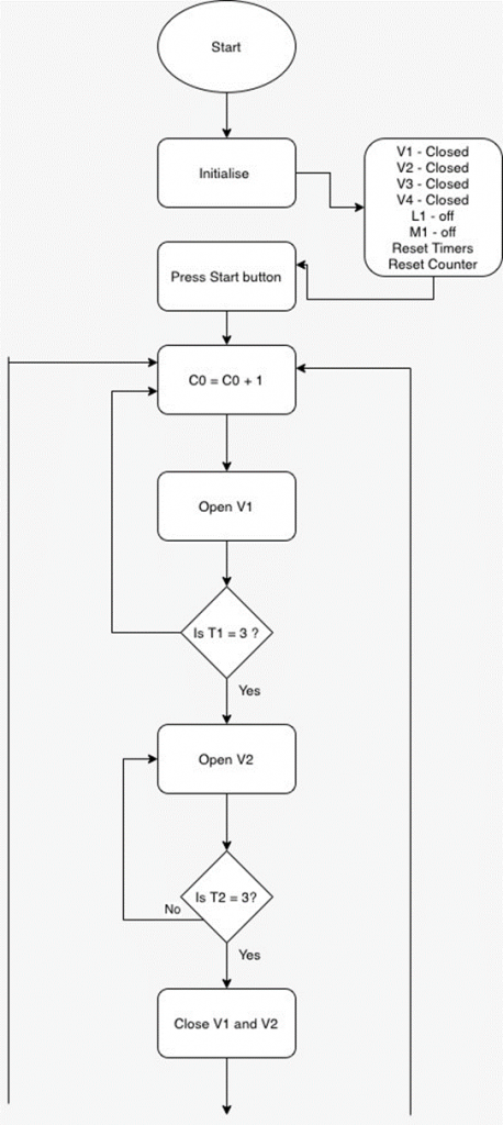
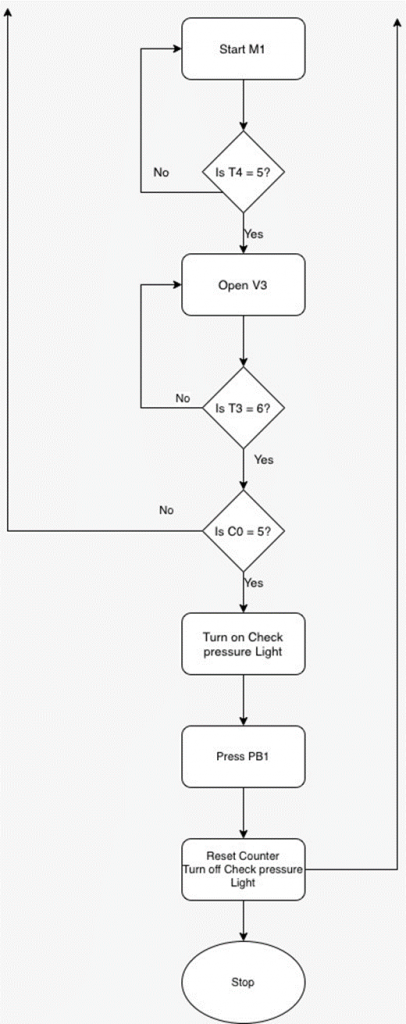
3.1 Normal Mixing Cycle
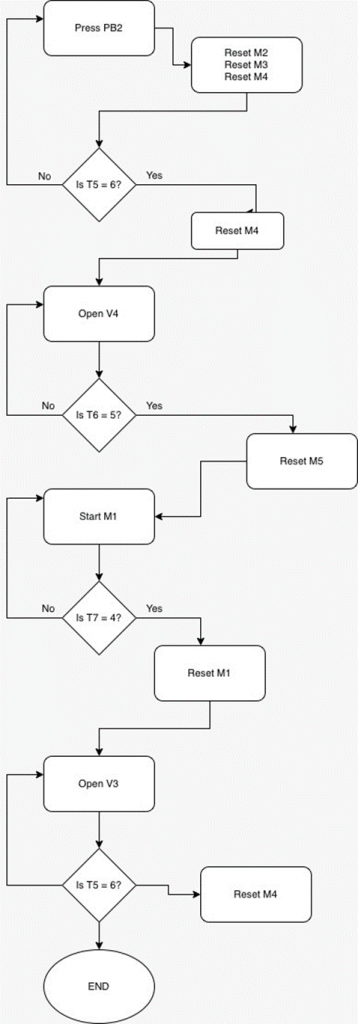
3.2 Cleaning Cycle
4 Process Description
The process was designed with three parts, the normal cycle, the cleaning cycle, and the visualisation. The normal cycle contains the normal mixing process the industrial tank follows, the cleaning cycle contains the process followed to clean the tank and the visualisation contains components that have been added to aid visualisation during the simulation.
4.1 Normal Cycle
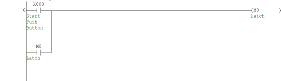
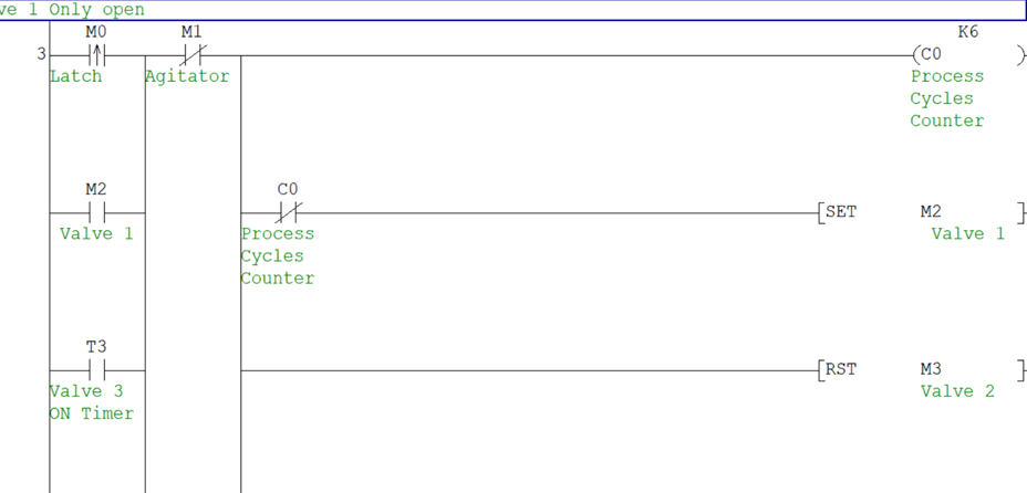
I divided the process into smaller stages. This helped me to work through the code gradually. The first stage in the process is when the start button is pressed. I added a Latch represented by M0 to the start button line, this Latch would ensure the system would keep running even after the start pushbutton is pressed and has returned to its normal state.
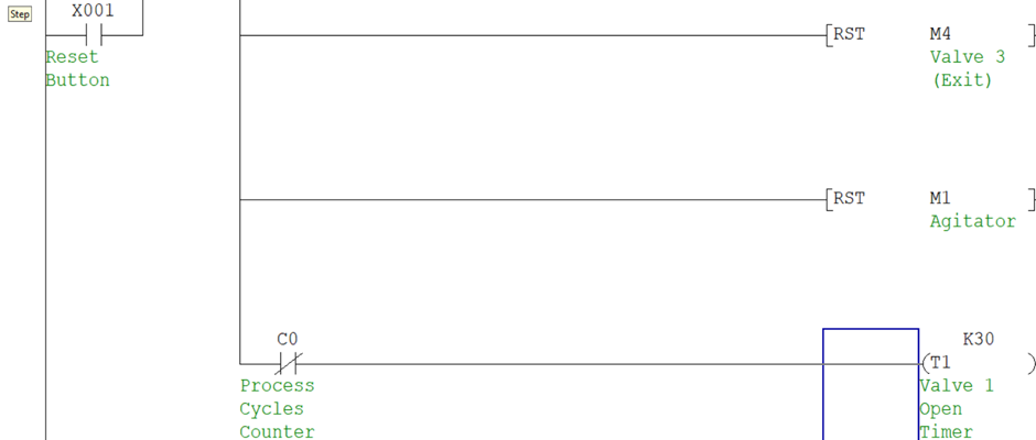
After the start button is pushed, the next stage is where only valve one is open. There are three components put in place to trigger this stage. First, the latch M0 can trigger it when the system starts for the first time. Secondly, the Valve 3 timer (T3) can trigger it when the contents of the tank have been emptied and a new cycle is about to begin. Third, it can be triggered when the PB1 is pressed to reset and restart the system. At the state of the process, it should not be able to run when the agitator mixer is on. Therefore, I add a normally closed contact for the agitator mixer along the line to ensure that if it is on, the process will end there. Once any of the three components are on and the agitator motor is off, the process can continue. Next, the counter is turned on and begins to count the number of cycles completed. I added a normally closed component of the counter to the line of M2 and T1 to ensure that when the counter reaches 5, it will stop Valve 1 from opening and T1 from starting. If the count on the counter is less than 5, Valve 1 and T1 are turned on. Since all other components should be off in this stage, I reset all the other components.
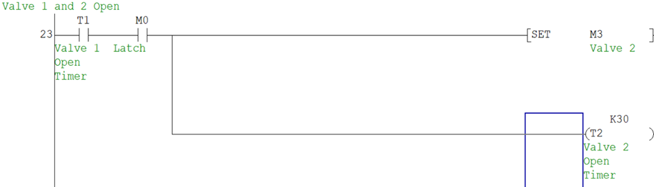
After 3 seconds, T1 turns on and it triggers Valve 2 to open and T2 begins to count.
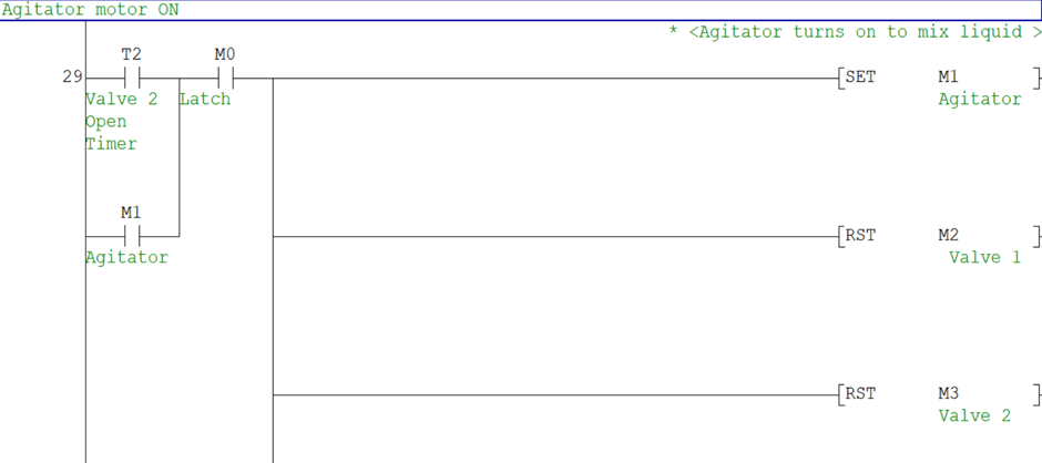
After another 3 seconds, T2 turns on and it triggers Valves 1 and Valve 2 to be closed and then turns on the agitator motor. T4 then begins to count.
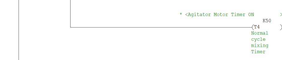
After 5 seconds, T4 turns on and it triggers the reset for the agitator motor and opens Valve 3. I added a normally closed contact component of T1 to the line of T3, to ensure that it does not start when Valve 1 opens. If T1 is in its normal state, T3 begins to count.
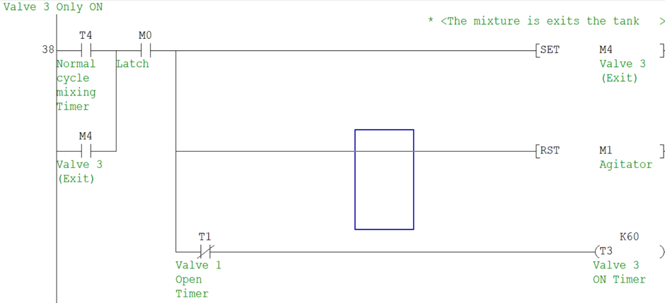
If the count is not up to 5 cycles, T3 will turn on and trigger the process to repeat itself as it is a trigger for the first stage of the process. When the count reaches 5 cycles, it stops the process and asks the operator to check the temperature and pressure of the system, this is indicated with the lamp turning on. M6 represents this lamp, and it is turned on when C0 is activated.
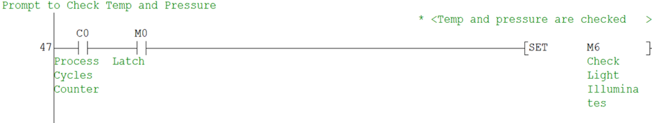
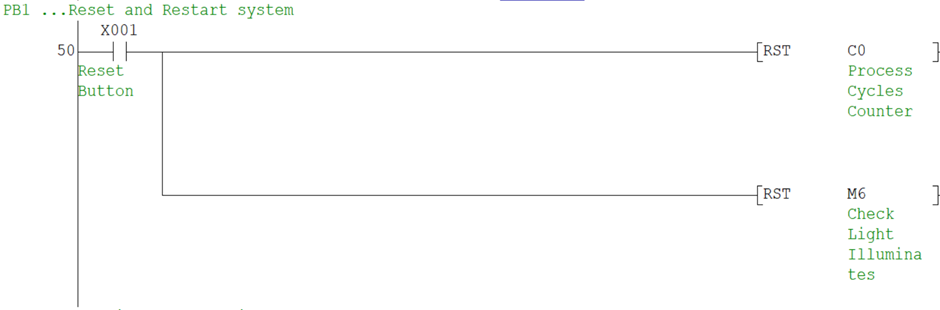
When the operator has checked the pressure and temperature, he can press the PB1 button to reset and restart the system. This resets C0 to allow the process to start again as a new count would begin. M6 is also turned off. The system then starts again because PB1 is one of the triggers for the first stage where only valve 1 is open.
4.2 Cleaning cycle
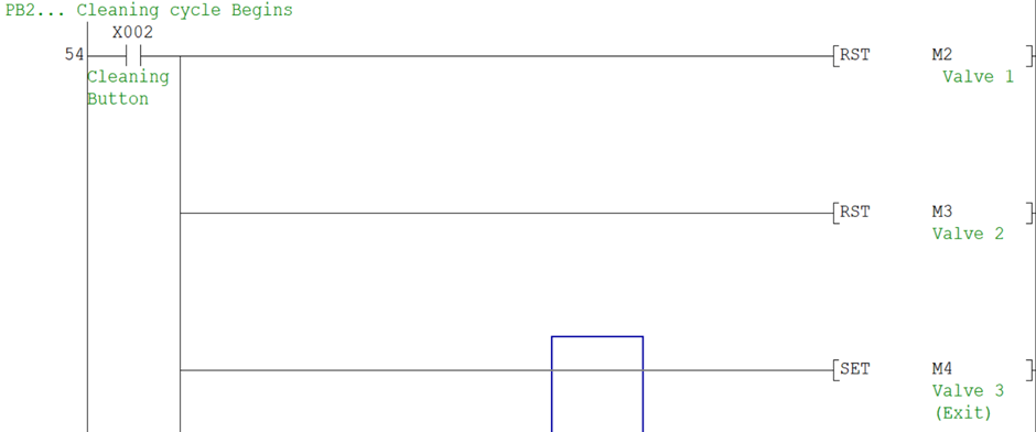
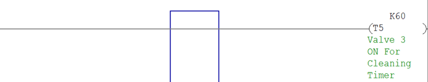
The Cleaning cycle starts when the PB2 button is pushed. First, Valve 1 and Valve 2 are closed, and then Valve 3 is turned on. T5 begins to count.
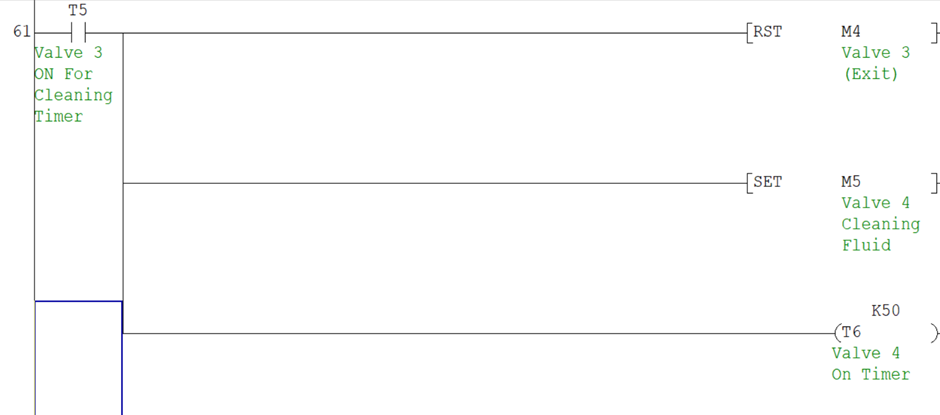
After 5 seconds T5 turns on and closes Valve 3, at this stage the tank is empty. Valve 4 is then opened to allow the cleaning fluid into the tank. T6 then begins to count.
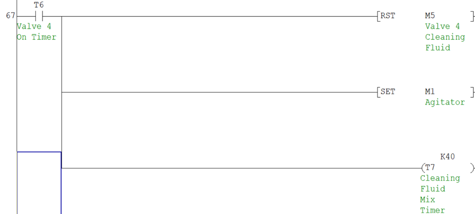
After 5 seconds T6 turns on and closes Valve 4, and then the agitator motor is turned on to mix the cleaning fluid in the tank. T7 begins to count.
After 4 seconds T7 turns on and turns off the agitator motor, and then Valve 3 is opened to remove the contents in the tank. T8 begins to count.
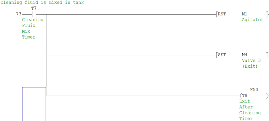
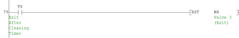
After 5 seconds, T8 turns on and closes Valve 3.
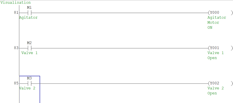
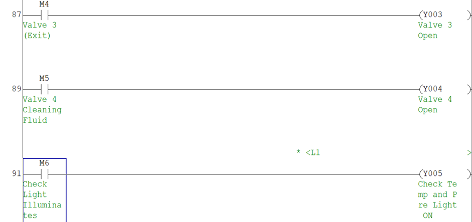
4.3 Visualisation
To help visualise the process during the simulation, lamps were used to represent the state of some of the components. The auxiliary motors of Valve 1, Valve 2, Valve3, and Valve 4 and the agitator motor were set to trigger their lamps when they are on.
5 Conclusion and Reflection
This was a very exciting project; the process was easy to follow, and I was able to complete the code very quickly. I was able to extract concepts from some of the example projects I did in class. Dividing the process into different stages made it easier to solve. One of the challenges faced while writing the system was, how to get the PB1 button to reset and restart the system. To solve this problem, I added PB1 as one of the triggers to start the first stage of the program. This meant that when PB1 is pressed it will be able to restart the system after resetting it.
An improvement to this system would be to set the system to automatically check the pressure and temperature are fine every 5 cycles interval so that it can continue the process and save more time.