
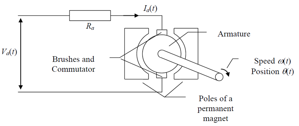
1 (a)

Where Va(t) is the Input Armature Voltage and outputs 0(t) is the Position and W(t) is motor velocity.
2 (b)

Figure 2: Plot of The Motor Velocity and Position Against Time for 2 Seconds
Velocity at t = 1 second is 83.25
Position at t = 1 second is 71.44
3 (c)
3.1 Laplace transform of the motor Velocity
To solve for the transfer function of the motor velocity, I used the Laplace transform table and some algebraic manipulation; The calculations are shown below.

Given Km =0.06, Kb =0.06, J = 6.2 * 10-4 and Ra= 1.2 Subtituting there values into the equation:

Therefore, The transfer function G(s)

3.2 Laplace transform of the motor shaft position
To solve for the transfer function of the motor shaft position. First, I used the second equation given that showed the relationship between the position of the motor shaft and the motor velocity to derive equations 2 and 3. Then I substituted the value into the equation that relates the armature voltage and motor velocity which I named Equation 1. Finally, using the Laplace transform table and some algebraic manipulation, I was then able to calculate the Laplace transform of the equation. The calculations are shown below.

Given Km =0.06, Kb =0.06, J = 6.2 * 10-4 and Ra= 1.2 Subtituting there values into the equation:

4 (d)
4.1 PI Controller for Motor Velocity
By applying the 1st order reaction curve method formulas, I was able to model a transfer function for the process and then used this to solve for the gain values for the PI Controller. The full calculation is shown below. First, I calculated the gain of the system and then obtained the values of t1 and t2 from the graph of the process. Next, using these values I was able to get the and d values. Then, I substituted them into the transfer function. Finally, I used the formula for the proportional and integral gain of a first-order system to calculate the required gains. The full calculation is shown below.

From the graph of the process
28.3% of 16.67 = 4.71761
68.2% of 16.67 = 10.53544
Therefore, the values of t2 and t1 are:
t1 = 1.069 t2 = 1.208

= 1.5(1.208 – 1.069)
= 1.5(0.139) = 0.2085

= 1.5(1.069 – 0.402667)
= 1.5(0.66633) = 0.9995

4.2 PD Controller for Position
By applying the 2nd order reaction curve method formulas, I was able to model a transfer function for the process and then used this to solve for the gain values of the PD Controller. First, I calculated the gain of the system and then obtained the values of t1,t2 and t3 from the graph of the process. Using these values, I was able to get the α and β values. Next, I used an Excel sheet to calculate the values of the damping ratio, natural frequency, and delay. Then, I substituted the values of the damping ratio, natural frequency, and delay into the transfer function. Using the values of the damping ratio, natural frequency and delay I was able to calculate the proportional and differential gain. The full calculation is shown below.

From the graph of the process
14% of 146 = 20.44
55% of 146 = 80.3
91% of 146 = 132.86
Therefore, the values of t2 and t1 are:
t1 = 2.431 t2 = 6.020 t3 =9.177


5 (e)
5.1 Motor Velocity W(t) Controller


Figure 11: Open Loop Response Figure

Figure 12: Closed Loop Response Figure
5.2 Motor Shaft Position O(t) Controller

Figure 13: Copy of The Simulink Model for the Position Controller

Figure 14: Open Loop Response Figure

Figure 15: Closed Loop Response Figure